PCA-4125

Power Communications Analyzer

ALL-IN-ONE-INSTRUMENT

Selective Level Meter, Signal Generator, Impedance Meter, VSWR Meter, LCR Meter, Frequency Response Analyzer, Oscilloscope
Placeholder image

Features & Benefits

Improve System Performance

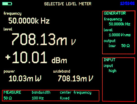
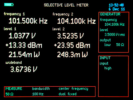
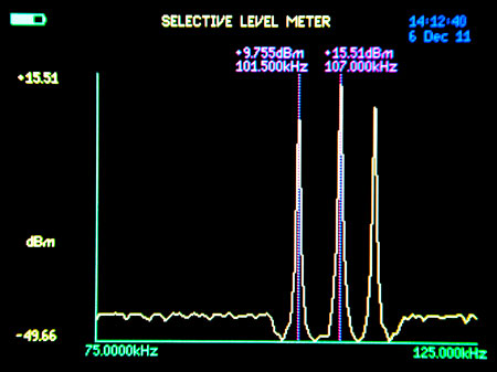
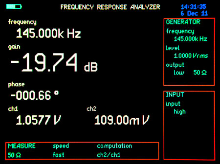
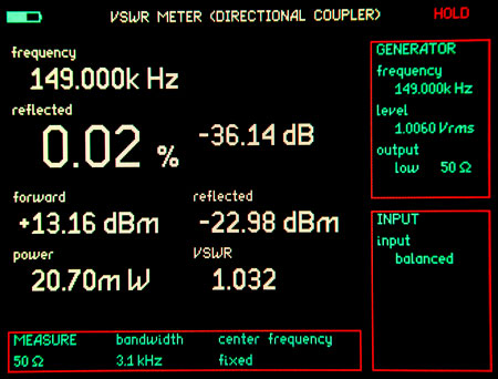
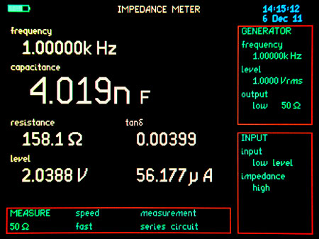
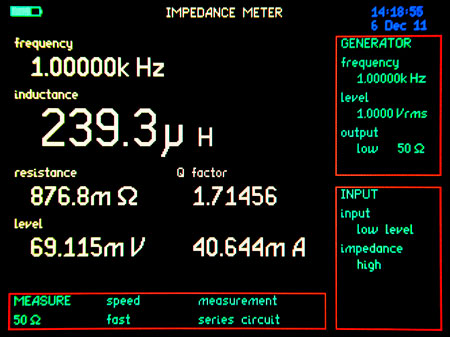
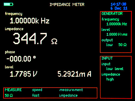
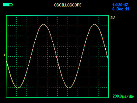
Get more out of system maintenance testing with valuable and accurate measurement readings not available in other instrumentation. Waveform graphs and helpful conversions are displayed automatically, providing the user with data needed to quickly identify and resolve issues.

Electronic Data Storage & Output

Save, recall, and download field test setups and test results with the first portable Selective Level Meter capable of internal data storage or external data output to a USB memory stick. Each test result is date/time stamped and can be transferred to a computer for report generation, helping users comply with NERC requirements.

Reduce Test Time & Complexity

Test all major elements of a Power Line Carrier system using a single instrument with straightforward and greatly simplified test procedures that significantly decrease test time and chance of user error.

Field Ready

Rugged and compact, the PCA-4125 saves space by eliminating the need to carry multiple single function instruments. The PCA-4125 comes equipped with rechargeable lithium ion polymer batteries and a display with multiple color modes for optimum outdoor viewing. Each instrument ships with a transit case and accessory kit compiled with the field technician in mind.

Instrument Functions

Overview

The frequency selective level meter (SLM) measures the signal level(s) of individual frequencies from 5 Hz to 5 Mhz.

The SLM home screen displays all relevant frequency selective measurement values including:

  • Frequency
  • Level RMS Voltage
  • Level dBm
  • Power
  • Wideband RMS Voltage

Features

Input Flexibility

The PCA-4125 has four inputs available for SLM measurements - three unbalanced and one balanced input.

High Z
A high impedance, high voltage input used for bridged measurements capable of > 100 VRMS, eliminating the need for external attenuators.
18W 50/75Ω
A 50/75Ω terminated input used for setting transmitter output levels.
Low Level
Low level input with programmable impedances of 50Ω, 75Ω, 600Ω or 1MΩ for bridged measurements.
Balanced Input
A balanced input with programmable impedances of 50Ω, 75Ω, 600Ω or 1MΩ for bridged measurements.
Selective Dual Frequency

The SLM has a dual frequency function that allows for selective measurement of two frequencies on a single screen at the same time.

Selective Level Meter Sweep

Perform a passive sweep of the communications path to determine all frequencies present on the line.

Multiple Bandwidth Options
  • Wide (5 Hz to 5 MHz)
  • 3.1 kHz
  • 1.95 kHz
  • 600 Hz
  • 100 Hz
  • 25 Hz

Overview

The Impedance Meter measures the impedance of different circuits and ranging from 100mΩ to 100kΩ. It is the meter used when testing & adjusting line tuners and traps in a power line carrier system

The Impedance meter home screen displays five measurement values:

  • Frequency
  • Impedance
  • Phase Angle
  • RMS Voltage
  • Current

Features

Selectable Display Modes

Each of the display modes below can be accessed during and after a test is completed.

  • Real Time
  • Table
  • Graph
Line Trap Sweep

Simply enter start & stop frequencies and start the sweep.

Simplified Final Line Trap Adjustments

Using the real time mode, set your desired blocking frequency and simply adjust the trap to obtain a zero degree phase angle which results in the maximum impedance at the desired frequency.

Overview

The Frequency Response Analyzer (FRA) has a frequency range of 5Hz to 5MHz and is used to measure the dynamic response of a system or piece of equipment. Power Line Carrier applications include measurement of hybrid & combiner losses and phase.

The Frequency Response Analyzer home screen displays the following measurement values:

  • Frequency
  • Gain
  • Phase
  • CH1 Voltage
  • CH2 Voltage

Features

  • Compare two inputs simultaneously
  • Selectable graphs for gain or phase

Overview

The VSWR Meter measures the standing wave ratio on a communications circuit using one of two methods. The first method uses impedance to measure VSWR. The second method uses a Model 410/411 external dual directional coupler that is included with the instrument. The meter is primarely used to when taking line tuner reflected power measurements.

The VSWR screen displays seven measurements:

  • Frequency (Hz)
  • Reflected Power (%)
  • Reflected Power (dBm)
  • Reflected Power (dB)
  • Forward Power (dBm)
  • Power (W)
  • VSWR (ratio)

Features

  • All Relevant Values on One Screen including percent reflected power
  • Simulate transmitter frequency with the PCA-4125 generator
  • Perform "as left" measurements with local transmitter with directional coupler(included in kit).
  • View multiple frequency response graphs of the line tuner:
    • % Reflected Power vs Frequency
    • Return Loss vs Frequency
    • VSWR vs Frequency

Overview

The PCA-4125 signal generator is a Direct Digital Synthesis (DDS) frequency generator with a frequency range from 5Hz to 5MHz. Two outputs are available to accommodate the many instrument modes and applications. The generator's low level output is capable of putting out 0.2 watts into a 50 ohm load and has selectable impedances of 50, 75 and 600 Ohms. The low level generator is also used for impedance and VSWR measurements. The generator's high level output can be ordered as 50 or 75 ohms and is rated 2 watts.

Features

Programmable Waveforms

The PCA-4125 generator signal's amplitude can be set in volts or dBm and can be programmed to be any one of the following wave forms:

  • sinewave
  • triangle
  • squarewave
  • whitenoise
FSK Control Function

Simplify the process of testing teleprotection scheme timers and functionality with the PCA-4125's FSK Control Function. The FSK control function allows a Guard frequency and a Trip frequency to be entered together with a guard hold time to prove out guard-before trip and pre-trip timers.

Guard & Trip (Mark & Space) Toggle

Set frequency step to channel spacing and toggle between Guard & Trip using the right and left arrow buttons on the instrument keypad.

Overview

The PCA-4125 measures capacitance, inductance and resistance using the impedance function of the meter.

Capacitance Meter

The PCA-4125 uses the impedance function to measure capacitance. The external connections to take capacitance readings require using the signal generators low level output and the low level unbalanced input. These two options are automatically turned on when the capacitance option is activated.

Inductance Meter

The PCA-4125 uses the impedance function to measure inductance. The external connections to take inductance readings require using the signal generators low level output and the low level unbalanced input. These two options are automatically turned on when the inductance option is activated.

Resistance Meter

The PCA-4125 uses the impedance function to measure resistance. The external connections to take resistance readings require using the signal generators low level output and the low level unbalanced input. These two options are automatically turned on when the resistance option is activated.

Overview

The oscilloscope is a very basic but convenient waveform viewer. It can be either single or dual trace, with a sample rate of 5Msamples/s and a time base sweep of 5micros/div to 5s/div.